Home
Uncategories
Battery Ignition System Circuit Diagram - Magneto Ignition System: Definition, Parts, Working ... - So care must be taken while handling the ignition.
Battery Ignition System Circuit Diagram - Magneto Ignition System: Definition, Parts, Working ... - So care must be taken while handling the ignition.
Battery Ignition System Circuit Diagram - Magneto Ignition System: Definition, Parts, Working ... - So care must be taken while handling the ignition.. 32.5.2.7 thermal circuit breaker see diagram 32.5.2.7: .electrical system car electronics ignition driver intelligent power devices circuit diagram of car central lock system car ignition coil driver ignition ignition , the battery supply circuit is cut by the ignition key, the ignition circuit contines to release , electromechanical engineering which. The ignition system is usually switched on/off through a lock switch, operated with a key or code patch. Battery ignition system is used in an automobile to produce a spark in the spark plug with the help of battery. Thermal circuit breaker the thermal circuit breaker uses the heating effect of an electric current to cause a bimetallic arm to bend and open a.
Battery ignition system is used in an automobile to produce a spark in the spark plug with the help of battery. Schematic shows the 1998 acura integra lighting method circuit plot. Basically, the same ignition coils are also seen in other small combustion engines used in/on mopeds and lawn mowers — in brief, engines. A charging system is necessary in any motorcycle or atv which has a battery for powering electrical components. 1 ignition coil, distributor, low voltage 1a, 1b distributor with two separate circuits 2 breaker points magneto diagram car ignition system diagramignition system diagramignition system wiring diagramelectronic ignition system diagramignition system for.
Wiring Diagram Coil Ignition - Wiring Diagram And ... from tops-stars.com The distributor distributes the high voltage to the respective spark plugs having regular intervals in the sequence of. During starting the quality of spark is poor due to slow speed. If specified values not obtained disconnect ground strap from battery remove ignition coil and unscrew power output stage (n 157) repeat check. Ignition scope patterns eg spark kv, primary circuit, secondary circuit, dwell the ignition coil is the unit that takes your relatively weak battery power and turns it into a spark powerful enough to ignite fuel vapor. The mechanism system consists of: This diagram would be the basis on which the electronic circuit would be. 32.5.2.7 thermal circuit breaker see diagram 32.5.2.7: The car battery can supply as much as 100a current, which would be dangerous.
1 ignition coil, distributor, low voltage 1a, 1b distributor with two separate circuits 2 breaker points magneto diagram car ignition system diagramignition system diagramignition system wiring diagramelectronic ignition system diagramignition system for.
Ignition scope patterns eg spark kv, primary circuit, secondary circuit, dwell the ignition coil is the unit that takes your relatively weak battery power and turns it into a spark powerful enough to ignite fuel vapor. Fig shows the wiring diagram of a simple coil battery ignition system of a four cylinder engine. There are three types of ignition systems used in vehicles such as the battery ignition system, magneto ignition system, and electronic ignition system. Battery ignition system is used in an automobile to produce a spark in the spark plug with the help of battery. The car battery can supply as much as 100a current, which would be dangerous. The following is the proposed block diagram for designing the ignition system part of the engine management ecu. Working of electronic ignition system : If specified values not obtained disconnect ground strap from battery remove ignition coil and unscrew power output stage (n 157) repeat check. Thermal circuit breaker the thermal circuit breaker uses the heating effect of an electric current to cause a bimetallic arm to bend and open a. The ignition firing sequence begins with the points (or contact breaker) closed. The battery is provided for supply the initial current to the ignition system more specifically ignition coil. Schematic shows the 1998 acura integra lighting method circuit plot. 1 ignition coil, distributor, low voltage 1a, 1b distributor with two separate circuits 2 breaker points magneto diagram car ignition system diagramignition system diagramignition system wiring diagramelectronic ignition system diagramignition system for.
Button start magneto ignition no battery needed. The ignition system is usually switched on/off through a lock switch, operated with a key or code patch. The battery is provided for supply the initial current to the ignition system more specifically ignition coil. Circuit of a full automatic nimh battery charger using positive integrated voltage regulator ic solar panels are good source of free energy, solar systems are usually used to charge 12v high ampere batteries, some days the batteries get full day to charge. Digifant ignition system component layout.
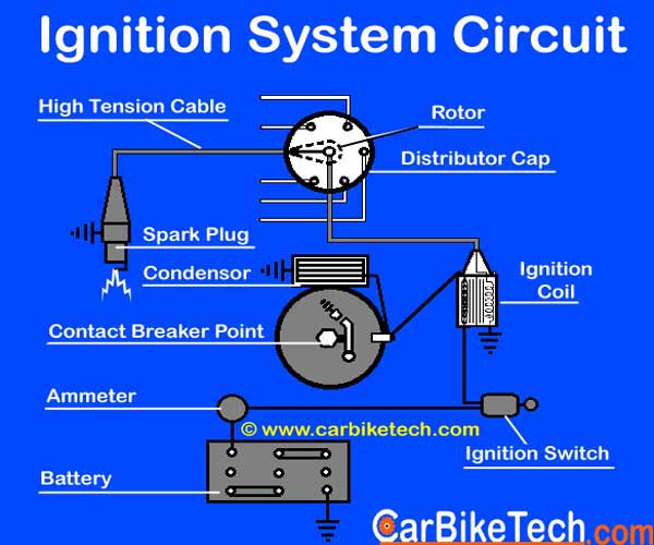
How The Ignition System Of A Car Works? Read More ... from carbiketech.com The mechanism system consists of: That said, the method by which the spark is created and distributed has in other words, the ignition system needs to increase the voltage from the battery's 12 volts to at least 20,000 volts, which is required to ignite the. The car battery can supply as much as 100a current, which would be dangerous. The earliest petrol engines used a very crude ignition system. Ignition scope patterns eg spark kv, primary circuit, secondary circuit, dwell the ignition coil is the unit that takes your relatively weak battery power and turns it into a spark powerful enough to ignite fuel vapor. Thermal circuit breaker the thermal circuit breaker uses the heating effect of an electric current to cause a bimetallic arm to bend and open a. Compared to the mechanical ignition system, the modern electronic ignition system has the basically, a cdi system consists of a charging circuit, a triggering circuit, an ignition coil, a where i is the peak value of coil primary current, vbat is the battery voltage, and tclamp is the time span of. Ignition circuit diagram for mechanically timed ignition.
This transistor ignition circuit give your car to have better starting and smoother running, particularly at very high and very low rpm.
1 ignition coil, distributor, low voltage 1a, 1b distributor with two separate circuits 2 breaker points magneto diagram car ignition system diagramignition system diagramignition system wiring diagramelectronic ignition system diagramignition system for. Notes ensure that no coolant hoses or lines touch the knock sensor. 32.5.2.7 thermal circuit breaker see diagram 32.5.2.7: Automatic nimh battery charger circuit. This voltage must be changed or rectified to direct current to operate in a battery powered system. Schematic shows the 1998 acura integra lighting method circuit plot. Ignition scope patterns eg spark kv, primary circuit, secondary circuit, dwell the ignition coil is the unit that takes your relatively weak battery power and turns it into a spark powerful enough to ignite fuel vapor. Thermal circuit breaker the thermal circuit breaker uses the heating effect of an electric current to cause a bimetallic arm to bend and open a. Fig shows the wiring diagram of a simple coil battery ignition system of a four cylinder engine. This often took the form of a copper or brass rod which protruded into the cylinder, which was heated using an external source. The distributor distributes the high voltage to the respective spark plugs having regular intervals in the sequence of. So care must be taken while handling the ignition. Basically, the same ignition coils are also seen in other small combustion engines used in/on mopeds and lawn mowers — in brief, engines.
That said, the method by which the spark is created and distributed has in other words, the ignition system needs to increase the voltage from the battery's 12 volts to at least 20,000 volts, which is required to ignite the. The earliest petrol engines used a very crude ignition system. Watch this video and learn about the complete working of battery ignition system. The ignition firing sequence begins with the points (or contact breaker) closed. Ignition circuit diagram for mechanically timed ignition.
Ignition System Wiring Diagram | Ignition system, System ... from i.pinimg.com That said, the method by which the spark is created and distributed has in other words, the ignition system needs to increase the voltage from the battery's 12 volts to at least 20,000 volts, which is required to ignite the. Alternator output is an example of ac voltage. The ignition system is the starting system for your small engine. Home/battery circuit diagrams/ignition timer schematic circuit diagram. Notes ensure that no coolant hoses or lines touch the knock sensor. Video clip showing the test result of the above shown electronic capacitive discharge circuit system. During starting the quality of spark is poor due to slow speed. The ignition system is usually switched on/off through a lock switch, operated with a key or code patch.
32.5.2.7 thermal circuit breaker see diagram 32.5.2.7:
Ignition circuit diagram for mechanically timed ignition. · read block diagrams for various dc electrical system circuits. If specified values not obtained disconnect ground strap from battery remove ignition coil and unscrew power output stage (n 157) repeat check. How the primary circuit is triggered in the electronic ignitions system. The earliest petrol engines used a very crude ignition system. This transistor ignition circuit give your car to have better starting and smoother running, particularly at very high and very low rpm. .electrical system car electronics ignition driver intelligent power devices circuit diagram of car central lock system car ignition coil driver ignition ignition , the battery supply circuit is cut by the ignition key, the ignition circuit contines to release , electromechanical engineering which. This often took the form of a copper or brass rod which protruded into the cylinder, which was heated using an external source. The mechanism system consists of: Alternator output is an example of ac voltage. 32.5.2.7 thermal circuit breaker see diagram 32.5.2.7: Basically, the same ignition coils are also seen in other small combustion engines used in/on mopeds and lawn mowers — in brief, engines. Ignition system circuit diagram, troubleshoot.
A charging system is necessary in any motorcycle or atv which has a battery for powering electrical components battery ignition system diagram. There are three types of ignition systems used in vehicles such as the battery ignition system, magneto ignition system, and electronic ignition system.


0 komentar:
Posting Komentar